Input and Output
Contents
29. Input and Output#
Input/Output (I/O) devices are crucial to the operation of a computer. The data that a program processes — as well as the program binary itself — must be loaded into memory from some I/O device such as a disks, networks, or keyboard. Similarly, without a way to output the results of a computation to the monitors or to storage, those results would be lost.
One of the primary functions of the operating system is to manage these I/O devices. It should control access to them, as well as providing a consistent programming interface across a wide range of hardware devices with similar functionality but differing details.
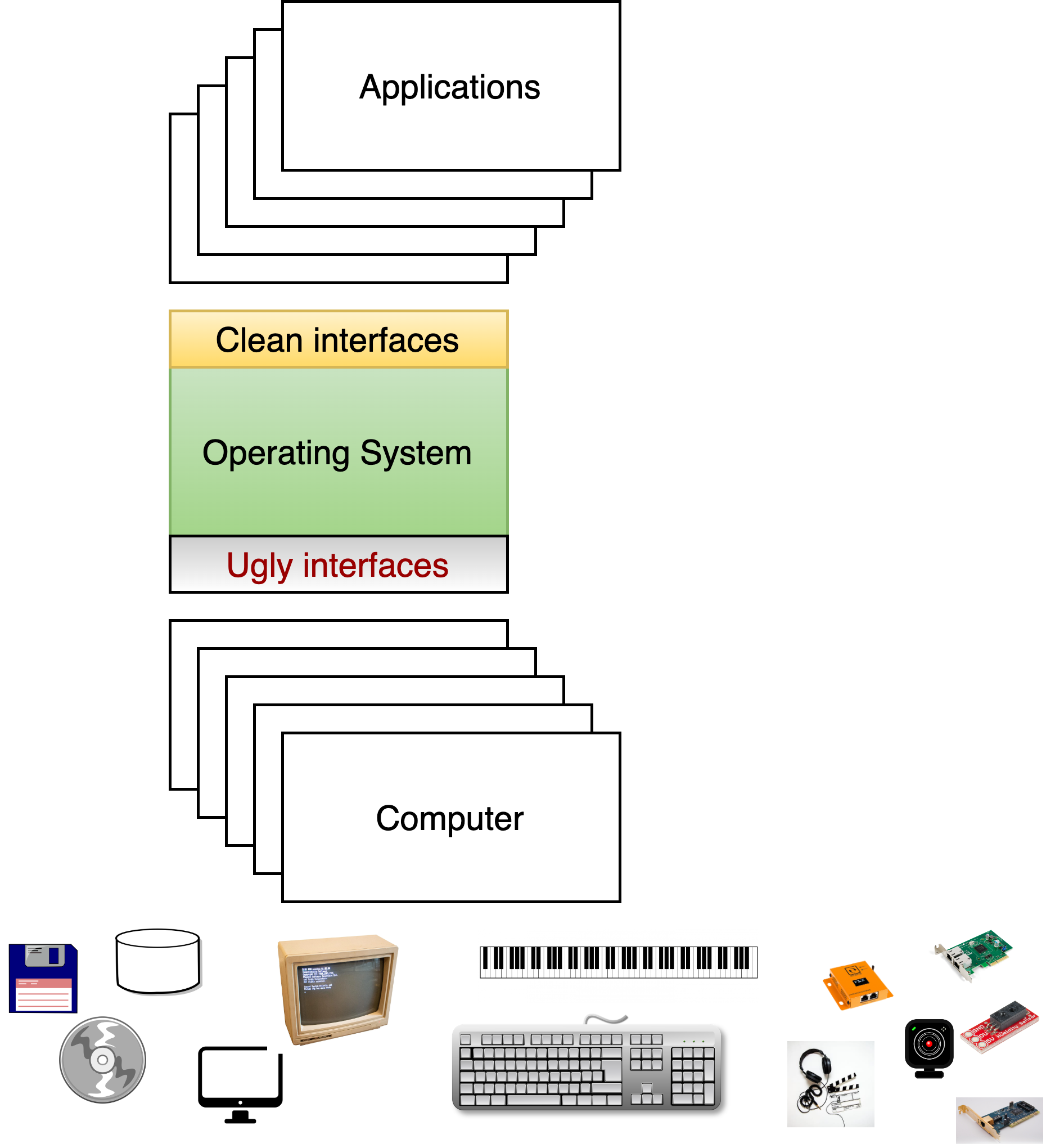
Fig. 29.1 Supporting devices#
We first describe the characteristics of device hardware, and then how the OS interacts with that hardware.
29.1. IO Hardware#
We outline structure of a standard computer, device controllers, how the OS interacts with the controller using port and memory mapped I/O, how interrupts work, and conclude with a discussion of Direct Memory Access (DMA).
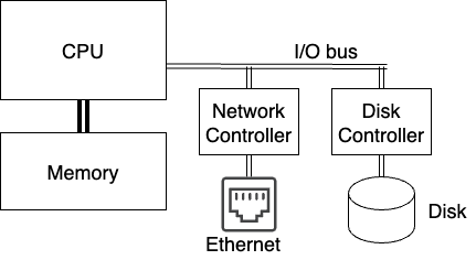
Fig. 29.2 An abstract model of a computer.#
29.1.1. Structure of a computer#
At the start of the course, we presented a simple model of hardware (Fig. 29.2) was discussed. The CPU is connected to high speed memory, and through a lower speed bus to a network controller and disk controller that are in turn connected to a network (ethernet in this case) and a disk.
Fig. 29.3 shows the more complicated architecture of a relatively modern Intel-architecture. Different parts of the system are connected by buses, or communication channels, operating at various speeds. The Front-Side Bus carries all memory transactions which miss in L1 and L2 cache, and the North Bridge directs these transactions to memory (DDR2 bus) or I/O devices (PCIe bus) based on their address. The PCI Express (PCIe) is somewhat slower than the front-side bus, but can be extended farther; it connects all the I/O devices on the system. In some cases (like USB and SATA), a controller connected to the PCIe bus (although typically located on the motherboard itself) may interface to a yet slower external interface. Finally, the ISA bus, used to connect slow devices like keyboards, is a vestige of the original IBM PC; for some reason, they’ve never moved some crucial system functions off of it, so it’s still needed.1
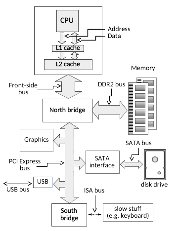
Fig. 29.3 A standard Intel PC Architecture#
29.1.2. Controllers#
I/O devices typically connected as PCI/ISA cards installed on the mother board have, in additional to their mechanical components, controllers that manage the device. The task of this controller is to convert from the operations on the bus to device specific operations. The processor interacts with these controllers by reading and writing controller registers.

Fig. 29.4 Registers of an Intel network interface card. It contains around 5600 32-bit registers broken down as shown. Note that complex OSes, like Linux, only initialize around 1000 of these registers.#
To understand how complex modern devices can be, consider Fig. 29.4 that shows the breakdown of registers of a modern Intel NIC. There are over 5600 32 bit registers, providing enormous complexity in how the OS can configure and interact with the device. As a result, these controllers often have a general purpose CPU, a fair amount of RAM to buffer data going to/from the device, and often some permanent flash storage. The software that used on these processors, typically referred to as firmware is complex enough that it must be regularly upgraded to deal with bugs. This turns out to be a massive attack surface in today’s computers. For example the following story describes one technique that has been used by the NSA to embed undetectable spyware on disks.
29.1.3. Accessing the controller#
The OS talks with the controller by reading and writing registers of the device and by reading and writing data that is buffered by the controller. Certain CPUs, including Intel architecture, contain support for a secondary I/O bus, with a smaller address width and accessed via special instructions. (e.g. “IN 0x100” to read a byte from I/O location 0x100, which has nothing to do with reading a byte from memory location 0x100). This is typically called port mapped I/O.
All architectures support Memory-mapped I/O, where devices can be mapped in the physical memory space and accessed via standard load and store instructions.
Depending on the system architecture, the device may be responsible for decoding the full address and determining when it has been selected, or a select signal may indicate when a particular slot on the bus is being accessed. Almost all computers today use a version of the PCI bus, which uses memory-mapped access, and at boot time, assigns each I/O device a physical address range to which it should respond.
29.1.4. Polled vs. Interrupt-driven I/O#
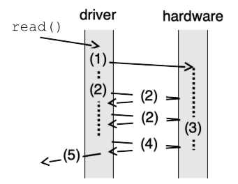
Fig. 29.5 Polled I/O#
The
simplest way to control an I/O device is for the CPU to issue commands
and then wait, polling a device status register until the operation is
complete. In Fig. 29.5 (a) an application requests I/O via e.g. a
read system call; the OS (step 1) then writes to the device command
register to start an operation, after which (step 2) it begins to poll
the status register to detect completion. Meanwhile (step 3) the device
carries out the operation, after which (step 4) polling by the OS
detects that it is complete, and finally (step 5) the original request
(e.g. read) can return to the application.
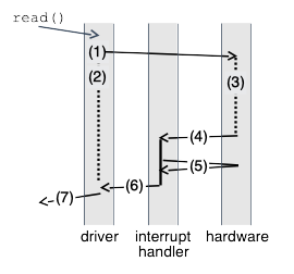
Fig. 29.6 Interrupt
driven I/O#
The alternate is interrupt-driven I/O, as shown in Fig. 29.6 (b). After (step 1) issuing a request to the hardware, the OS (step 2) puts the calling process to sleep and switches to another process while (step 3) the hardware handles the request. When the I/O is complete, the device (step 4) raises an interrupt. The interrupt handler then finishes the request. In the illustrated example, the interrupt handler (step 5) reads data that has become available, and then (step 6) wakes the waiting process, which returns from the I/O call (step 7) and continues.
29.1.5. Interrupts#
We have already mentioned Interrupts many times, but nows a good time to flesh them out in a bit more detail. To handle asynchronous I/O events, CPUs provide an interrupt mechanism. In response to a signal from an I/O device the CPU executes an interrupt handler function, returning to its current execution when the handler is done. The CPU essentially performs a forced function call, saving the address of the next instruction on the stack and jumping to the interrupt handler; the difference is that instead of doing this in response to a CALL instruction, it does it at some arbitrary time (but between two instructions) when the interrupt signal is asserted.
Most CPUs have several interrupt inputs; these correspond to an interrupt vector table in memory, either at a fixed location or identified by a special register, giving the addresses of the corresponding interrupt handlers. As an example, below we see the corresponding table for an 8088 CPU as found in the original IBM PC, which provides handler addresses for external hardware interrupts as well as exceptions which halt normal program execution, such as dividing by zero or attempting to execute an illegal instruction.
  Index          Description          DOS name
  ------- ------------------------- ------------
  0            divide by zero
  1              single step
  2             non-maskable
  3              debug break
  4        debug break on overflow
  5               -unused-
  6            invalid instr.
  7               -unused-
  8             system timer            IRQ0
  9            keyboard input           IRQ1
  10           line printer 2        IRQ2, LPT2
  11            serial port 2        IRQ3, COM2
  12            serial port 1        IRQ4, COM1
  13              hard disk             IRQ5
  14             floppy disk            IRQ6
  15           line printer 1        IRQ7, LPT1
  16-         software-defined
  255            interrupts

  : 8086/8088 interrupts as defined by the IBM PC hardware.
The simplest interrupt-generating device is a timer, which does nothing except generate an interrupt at a periodic interval. As shown below, we see why it is called a timer—one of its most common uses is to keep track of time.
extern int time_in_ticks;
    timer_interrupt_handler() {
        time_in_ticks++;
    }
Another simple use for interrupts is for notification of keyboard input. Besides being useful for a “cancel” command like control-C, this is also very useful for type-ahead. On slower computers (e.g. the original IBM PC executed less than half a million instructions per second) a fast typist can hit multiple keys while a program is busy. A simple keyboard interface only holds one keystroke, causing additional ones to be lost. By using the keyboard interrupt, the operating system can read these keystrokes and save them, making them available to the program the next time it checks for input.
29.1.6. Direct Memory Access (DMA)#
The CPU could copying data between I/O devices and memory using normal memory load and store instructions. Such an approach works well on computers such as the Apple II or the original IBM PC which run at a few MHz, where the address and data buses can be extended at full speed to external I/O cards. A modern CPU runs at over 3 GHz, however; during a single clock cycle light can only travel about 4 inches, and electrical signals even less. Fig. 29.7 shows example latencies for a modern CPU (in this case an Intel i5, with L3 cache omitted) to read a data value from L1 and L2 cache, a random location in memory (sequential access is faster), and a register on a device on the PCIe bus. (e.g. the disk or ethernet controller) In such a system, reading data from a device in 4-byte words would result in a throughput of 5 words every microsecond, or 20MB/s — far slower than a modern network adapter or disk controller.
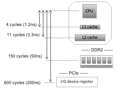
Fig. 29.7 Latency between CPU and various levels of memory/IO hierarchy#
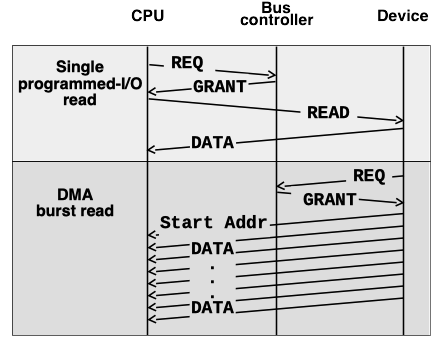
Fig. 29.8 DMA access for high-speed data transfer#
Almost all computers today use the PCIe bus. Transactions on the PCIe bus require a negotiation stage, when the CPU (or a device) requests access to bus resources, and then is able to perform a transaction after being granted access. In addition to basic read and write requests, the bus also supports Direct Memory Access (DMA), where I/O devices are able to read or write memory directly without CPU intervention. Fig. 29.8 shows a single programmed-I/O read (top) compared to a DMA burst transfer (bottom). While the read request requires a round trip to read each and every 4-byte word, once the DMA transfer is started it is able to transfer data at a rate limited by the maximum bus speed. (For an 8 or 16-lane PCIe card this limit is many GB/s)
A device typically requires multiple parameters to perform an operation and transfer the data to or from memory. In the case of a disk controller, for instance, these parameters would include the type of access (read or write), the disk locations to be accessed, and the memory address where data will be stored or retrieved from. Rather than writing each of these parameters individually to device registers, the parameters are typically combined in memory in what is called a DMA descriptor, such as the one shown in Fig. 29.9. A single write is then used to tell the device the address of this descriptor, and the device can read the entire descriptor in a single DMA read burst. In addition to being more efficient than multiple programmed I/O writes, this approach also allows multiple requests to be queued for a device. (In the case of queued disk commands, the device may even process multiple such requests simultaneously.) When an I/O completes, the device notifies the CPU via an interrupt, and writes status information (such as success/failure) into a field in the DMA descriptor. (or sometimes in a device register, for simple devices which do not allow multiple outstanding requests.) The interrupt handler can then determine which operations have completed, free their DMA descriptors, and notify any waiting processes.
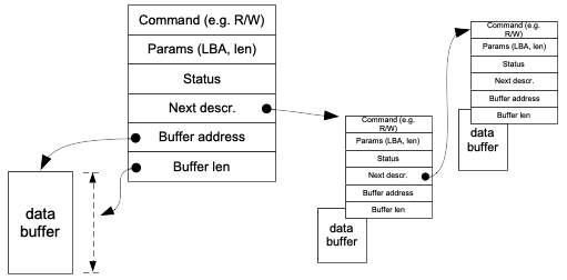
Fig. 29.9 List of typical DMA descriptors#
29.2. I/O Software and Device Drivers#
29.2.1. Fundamental Goals#
The operating system software that interacts with devices must:
Provide Device Independence: Programs should be able to access any similar device without worrying about the specific device available. For example, you should be able to read data from a floppy, hard drive, or CD-ROM without caring which device is available. As another example, your vim editor should be able to work if you are connecting a dumb terminal to your computer, or if you are using an emulated terminal provided by our course staff.
Handle Errors: Many errors are transient, and we want to handle them as close to the hardware as possible. For example, if a network is unavailable for a brief period of time, we don’t want to close all the connections. If we get an error reading a disk block, the OS might try re-reading assuming that there was a transient failure, or correct the error using some form of error correcting code.
Support synchronous interfaces: In reality, all devices interact with the OS asynchronously, where some character appears from a terminal when a user hits a key, or a network packet arrives when clients make new requests to a server. On the other hand, generally the programming interfaces users have are synchronous, for example, using a
readto a network socket or file system. The OS keeps translates between the blocking calls by applications and the innate events that come in from devices.Buffering: Related to asynchronous interactions, the operating system normally manages buffers to enable data to be transferred to and from the devices to match the performance needs of the device. We have already seen how memory management creates a massive buffer cache to buffer millions of blocks in memory. On the other hand, if a program is dumping huge files to a slow character device, the OS needs to buffer the data, and feed it to the device at the rate that the device can handle.
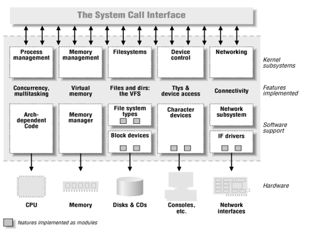
Fig. 29.10 OS layers#
To perform this functionality, much like when we discussed the VFS layer in file systems, as shown in Fig. 29.10 there is generic I/O code that provides services like buffering, generalized error reporting, and enables a set of standardized device interfaces. The three kind of standard device types are:
Block devices: e.g. SSDs, Hard drives, CDROMs
Character devices: ttys, pipes, …
Network devices: ethernet, token ring,…
There are many many devices drivers of each type. In fact, over 60% of Linux source code today with device drivers involving 10s of millions of LOC. Much of this code is provided by device manufacturers, and is the most buggy part of the OS.
Drivers responsibilities include:
Device initialization
Accept read-write request from the OS: i.e., take commands from higher levels in the OS and translate them into hardware requests
Start the device if necessary (e.g., start spinning the CD-ROM)
Check if device is available: if not, wait
Wait for results; typically blocking client request until interrupt occurs
Check for possible errors
Return results, and finally
Power management – put the device to sleep when it’s not being used
29.3. Putting it all together#
Fig. 29.11 illustrates the I/O process for a typical device from user-space application request through the driver, hardware I/O operation, interrupt, and finally back to user space.
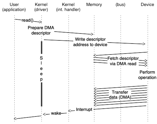
Fig. 29.11 Putting it together#
In more detail:
The user process executes a
readsystem call, which in turn invokes the driverreadoperation, found via thereadmethod of the file operations structure.The driver fills in a DMA descriptor (in motherboard RAM), writes the physical address of the descriptor to a device register (generating a Memory Write operation across the PCIe bus), and then goes to sleep.
The device issues a PCIe Memory Read Multiple command to read the DMA descriptor from RAM.
The device does some sort of I/O. (e.g. read from a disk, or receive a network packet)
A Memory Write and Invalidate operation is used to write the received data back across the PCIe bus to the motherboard RAM, and to tell the CPU to invalidate any cached copies of those addresses.
A hardware interrupt from the device causes the device driver interrupt handler to run.
The interrupt handler wakes up the original process, which is currently in kernel space in the device driver read method, in a call to something like
interruptible_sleep_on. After waking up, the read method copies the data to the user buffer and returns.
- 1
The primary difference between this figure and contemporary systems is that (a) the memory bus is DDR3 or DDR4, and (b) the north bridge is located on the CPU chip, with no external front-side bus.